- 您现在的位置:买卖IC网 > Sheet目录2006 > LTC2495CUHF#PBF (Linear Technology)IC ADC 16BIT W/PGA 38-QFN
LTC2495
2495fd
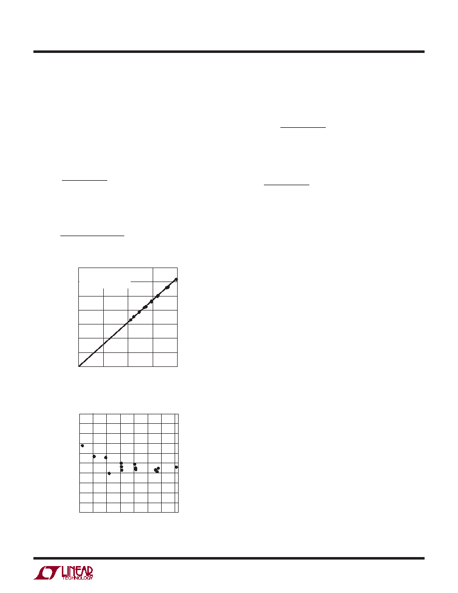
The internal temperature sensor output is 28mV at 27°C
(300°K), with a slope of 93.5V/°C independent of VREF
(see Figures 4 and 5). Slope calibration is not required if
the reference voltage (VREF) is known. A 5V reference has
a slope of 2.45 LSBs16/°C. The temperature is calculated
from the output code (where DATAOUT16 is the decimal
representationofthe16-bitresult)fora5Vreferenceusing
the following formula:
T
DATAOUT
in Kelvin
K =
16
2 45
.
If a different value of VREF is used, the temperature
output is:
T
DATAOUT
V
in Kelvin
K
REF
=
16
12 25
.
If the value of VREF is not known, the slope is determined
bymeasuringthetemperaturesensorataknowntempera-
ture TN (in K) and using the following formula:
SLOPE
DATAOUT
TN
=
16
This value of slope can be used to calculate further tem-
perature readings using:
T
DATAOUT
SLOPE
K =
16
All Kelvin temperature readings can be converted to TC
(°C) using the fundamental equation:
TC = TK – 273
Initiating a New Conversion
When the LTC2495 finishes a conversion, it automatically
enters the sleep state. Once in the sleep state, the device is
ready for a read operation. After the device acknowledges
a read request, the device exits the sleep state and enters
the data output state. The data output state concludes
and the LTC2495 starts a new conversion once a STOP
condition is issued by the master or all 24 bits of data are
read out of the device.
Duringthedatareadcycle,aSTOPcommandmaybeissued
by the master controller in order to start a new conversion
and abort the data transfer. This STOP command must be
issued during the ninth clock cycle of a byte read when
the bus is free (the ACK/NACK cycle).
LTC2495 Address
The LTC2495 has three address pins (CA0, CA1, CA2).
Each may be tied HIGH, LOW, or left floating enabling one
of 27 possible addresses (see Table 6).
In addition to the configurable addresses listed in Table 6,
the LTC2495 also contains a global address (1110111)
whichmaybeusedforsynchronizingmultipleLTC2495sor
otherLTC24XXdelta-sigmaI2Cdevices(seeSynchronizing
Multiple LTC2495s with a Global Address Call section).
applications inForMation
Figure 4. Internal PTAT Digital Output vs Temperature
Figure 5. Absolute Temperature Error
TEMPERATURE (K)
0
DA
TAOUT
16
450
600
750
900
1050
400
2495 F04
300
0
300
200
100
150
VCC = 5V
VREF = 5V
SLOPE = 2.45 LSB16/K
TEMPERATURE (°C)
–55 –30
–5
ABSOLUTE
ERROR
(°C)
5
4
3
2
1
–4
–3
–2
–1
0
120
95
70
45
20
2495 F05
–5
发布紧急采购,3分钟左右您将得到回复。
相关PDF资料
LTC2496IUHF#TRPBF
IC ADC 16BIT DELTA SIG 38-QFN
LTC2498IUHF#TRPBF
IC ADC 24BIT 16CH 38-QFN
LTC2600IUFD#PBF
IC DAC OCTAL R-R 16BIT 20-QFN
LTC2602IMS8#TRPBF
IC DAC 16BIT DUAL R-R VOUT 8MSOP
LTC2604IGN-1#TRPBF
IC DAC 16BIT QUAD R-R OUT 16SSOP
LTC2605IGN-1#TRPBF
IC DAC 16BIT OCT I2C 16-SSOP
LTC2606IDD#TRPBF
IC DAC 16BIT I2C V-OUT 10-DFN
LTC2607IDE#TRPBF
IC DAC 16BIT R-R I2C 12-DFN
相关代理商/技术参数
LTC2495CUHF#TRPBF
功能描述:IC ADC 16BIT W/PGA 38-QFN RoHS:是 类别:集成电路 (IC) >> 数据采集 - 模数转换器 系列:- 标准包装:2,500 系列:- 位数:16 采样率(每秒):15 数据接口:MICROWIRE?,串行,SPI? 转换器数目:1 功率耗散(最大):480µW 电压电源:单电源 工作温度:-40°C ~ 85°C 安装类型:表面贴装 封装/外壳:38-WFQFN 裸露焊盘 供应商设备封装:38-QFN(5x7) 包装:带卷 (TR) 输入数目和类型:16 个单端,双极;8 个差分,双极 配用:DC1011A-C-ND - BOARD DELTA SIGMA ADC LTC2494
LTC2495IUHF#PBF
功能描述:IC ADC 16BIT W/PGA 38-QFN RoHS:是 类别:集成电路 (IC) >> 数据采集 - 模数转换器 系列:- 标准包装:1 系列:microPOWER™ 位数:8 采样率(每秒):1M 数据接口:串行,SPI? 转换器数目:1 功率耗散(最大):- 电压电源:模拟和数字 工作温度:-40°C ~ 125°C 安装类型:表面贴装 封装/外壳:24-VFQFN 裸露焊盘 供应商设备封装:24-VQFN 裸露焊盘(4x4) 包装:Digi-Reel® 输入数目和类型:8 个单端,单极 产品目录页面:892 (CN2011-ZH PDF) 其它名称:296-25851-6
LTC2495IUHF#TRPBF
功能描述:IC ADC 16BIT W/PGA 38-QFN RoHS:是 类别:集成电路 (IC) >> 数据采集 - 模数转换器 系列:- 标准包装:1,000 系列:- 位数:16 采样率(每秒):45k 数据接口:串行 转换器数目:2 功率耗散(最大):315mW 电压电源:模拟和数字 工作温度:0°C ~ 70°C 安装类型:表面贴装 封装/外壳:28-SOIC(0.295",7.50mm 宽) 供应商设备封装:28-SOIC W 包装:带卷 (TR) 输入数目和类型:2 个单端,单极
LTC2496CUHF#PBF
功能描述:IC ADC 16BIT DELTA SIG 38-QFN RoHS:是 类别:集成电路 (IC) >> 数据采集 - 模数转换器 系列:- 标准包装:1 系列:microPOWER™ 位数:8 采样率(每秒):1M 数据接口:串行,SPI? 转换器数目:1 功率耗散(最大):- 电压电源:模拟和数字 工作温度:-40°C ~ 125°C 安装类型:表面贴装 封装/外壳:24-VFQFN 裸露焊盘 供应商设备封装:24-VQFN 裸露焊盘(4x4) 包装:Digi-Reel® 输入数目和类型:8 个单端,单极 产品目录页面:892 (CN2011-ZH PDF) 其它名称:296-25851-6
LTC2496CUHF#TRPBF
功能描述:IC ADC 16BIT DELTA SIG 38-QFN RoHS:是 类别:集成电路 (IC) >> 数据采集 - 模数转换器 系列:- 标准包装:2,500 系列:- 位数:16 采样率(每秒):15 数据接口:MICROWIRE?,串行,SPI? 转换器数目:1 功率耗散(最大):480µW 电压电源:单电源 工作温度:-40°C ~ 85°C 安装类型:表面贴装 封装/外壳:38-WFQFN 裸露焊盘 供应商设备封装:38-QFN(5x7) 包装:带卷 (TR) 输入数目和类型:16 个单端,双极;8 个差分,双极 配用:DC1011A-C-ND - BOARD DELTA SIGMA ADC LTC2494
LTC2496IUHF#PBF
功能描述:IC ADC 16BIT DELTA SIG 38-QFN RoHS:是 类别:集成电路 (IC) >> 数据采集 - 模数转换器 系列:- 标准包装:2,500 系列:- 位数:16 采样率(每秒):15 数据接口:MICROWIRE?,串行,SPI? 转换器数目:1 功率耗散(最大):480µW 电压电源:单电源 工作温度:-40°C ~ 85°C 安装类型:表面贴装 封装/外壳:38-WFQFN 裸露焊盘 供应商设备封装:38-QFN(5x7) 包装:带卷 (TR) 输入数目和类型:16 个单端,双极;8 个差分,双极 配用:DC1011A-C-ND - BOARD DELTA SIGMA ADC LTC2494
LTC2496IUHF#TRPBF
功能描述:IC ADC 16BIT DELTA SIG 38-QFN RoHS:是 类别:集成电路 (IC) >> 数据采集 - 模数转换器 系列:- 标准包装:2,500 系列:- 位数:16 采样率(每秒):15 数据接口:MICROWIRE?,串行,SPI? 转换器数目:1 功率耗散(最大):480µW 电压电源:单电源 工作温度:-40°C ~ 85°C 安装类型:表面贴装 封装/外壳:38-WFQFN 裸露焊盘 供应商设备封装:38-QFN(5x7) 包装:带卷 (TR) 输入数目和类型:16 个单端,双极;8 个差分,双极 配用:DC1011A-C-ND - BOARD DELTA SIGMA ADC LTC2494
LTC2497CUHF#PBF
功能描述:IC ADC 16BIT W/PGA 38-QFN RoHS:是 类别:集成电路 (IC) >> 数据采集 - 模数转换器 系列:- 标准包装:1 系列:microPOWER™ 位数:8 采样率(每秒):1M 数据接口:串行,SPI? 转换器数目:1 功率耗散(最大):- 电压电源:模拟和数字 工作温度:-40°C ~ 125°C 安装类型:表面贴装 封装/外壳:24-VFQFN 裸露焊盘 供应商设备封装:24-VQFN 裸露焊盘(4x4) 包装:Digi-Reel® 输入数目和类型:8 个单端,单极 产品目录页面:892 (CN2011-ZH PDF) 其它名称:296-25851-6